02 | 正运动学 - 已知角度求末端位姿 
约 3971 个字 35 行代码 预计阅读时间 16 分钟
本章的正运动学问题,就是将关节空间转化到笛卡尔空间当中去。
关节空间和笛卡尔空间
参数是关节的角度(旋转关节)或位移(移动关节)
关节空间分析是机器人运动学和控制的基础,它为控制算法和路径规划提供了一个直观的框架。
参数是 x, y, z 坐标和欧拉角或四元数,描述末端执行器的位置和方向。
笛卡尔空间分析为机器人的任务规划和执行提供了一个直观和可视化的框架,它使得能够直接描述和控制机器人在物理世界中的运动。
我们的目的就是获取机械臂末端相对于机械臂基座的位姿,首先要建立起连杆之间的变换关系。需要搞明白连杆坐标系的建立以及变换(先建立,再变换)
主要内容
- 连体坐标系的建立 —— MDH 和 SDH、运动学参量表的列写
- 连体坐标系的变换 —— 齐次变换矩阵相乘
- 正运动学问题:几何法、矩阵法

连体坐标系建立 
我觉得下面这一篇博文图片和解释比较清楚,这里要着重区别一下连杆转角和关节角
坐标系建立规则( 非标准 D-HDenavit-Hartenberg 方法 )
- 根据题目信息确定式 R(revolute joint) 还是 P(prismatic joint) 固定在关节轴 i 上的坐标系命名为坐标系 \(\{i\}\)(轴 i 的方向由设计者给定)
- 先确定 \(Z\) 轴,坐标系 \(\{i\}\) 的 Z 轴与关节轴 \(\{i\}\) 的轴线重合
- 再确定原点,坐标系 \(\{i\}\) 的原点为公共垂线 \(a_i\) 与关节轴 \(\{i\}\) 轴线的交点
- 再确定 \(X\) 轴,\(\{i\}\) 的 X 轴与公共垂线 \(a_i\) 重合
- 最后确立 \(Y\) 轴,根据右手定则确定坐标系 \(\{i\}\) 的 Y 轴 ( 大拇指指向 \(Z\), 右手螺旋确定 )
机械臂基座和末端坐标系定义
固定在基座和末端的坐标系可以任意设定方向,但是要以问题简化为主
- 例如固定在基座的参考坐标系 \(\{0\}\) 的 Z0 轴与关节轴 1 方向一致
- 例如关节 n 的坐标系 \(\{n\}\) 与坐标系 \(\{n-1\}\) 的 X 轴一致
这样的 \(T\) 中的 \(R\) 部分就是一个单位阵,加上一个平移向量即可
标准 DH 和非标准 DH 的区别 
(1)固连坐标系不同
Stantard DH 方法关节 i 上固连的是 i-1 坐标系,即坐标系建在连杆的输出端;MDH 关节 i 上固连的是 i 坐标系,即坐标系建在连杆的输入端。
(2)坐标系变换顺序不同
Stantard DH 方法是 ZX 类变换:先绕着 i-1 坐标系的的 \(Z_{i-1}\) 轴旋转和平移,再绕着坐标系 i 的 \(X_i\) 轴进行旋转和平移
Modified DH 方法是 XZ 类变换:先绕着 i 坐标系的的 \(X_i\) 轴旋转和平移,再绕着坐标系 i 的 \(Z_i\) 轴进行旋转和平移;( 题目中使用这种方法 )
先把 Z 轴调整好,再调整 X 轴
运动学参量 
- 连杆扭转角 \(\alpha_{i-1}\):绕 \(X_{i-1}\) 轴,从 \(Z_{i-1}\) 轴旋转到 \(Z_i\) 轴的角度
- 连杆长度 \(a_{i-1}\):沿 \(X_{i-1}\) 轴,从 \(Z_{i-1}\) 轴移动到 \(Z_i\) 轴的距离(公垂线段为 0 的时候,当 \(a_{i-1} = 0\) 时,我们并不将零长度的 \(r_{O_{i-1}P_i}\) 视为传统的零向量,而是在与轴 \(i-1\) 和轴 \(i\) 同时垂直的方向中选一个作为 \(r_{O_{i-1}P_i}\) 的正方向)
- 连杆轴距 \(d_i\):沿 \(Z_{i-1}\) 轴,从 \(X_{i-1}\) 轴移动到 \(X_i\) 轴的距离
- 关节角 \(\theta_i\):沿 \(Z_{i-1}\) 轴,从 \(X_{i-1}\) 轴旋转到 \(X_i\) 轴的角度
参数表
a 和 d 是怎么来的?通常来讲,它们是机械设计的时候确认的设计参数,机械臂的生产产家会告诉你这些数值。还有一个方法,就是自己在机械臂上量出来……
实际使用中,机械臂的制造商通常会给你完整的 DH 参数表;实在没有,也有一些算法,通过控制关节运动的同时用外部装置准确测量 end effector 的位姿,解算出 DH 参数表。有时候,由于制造过程不可避免的误差、或长时间使用后机械结构的磨损,会导致原有 DH 参数表不够准确;这个时候也可以用类似的方法重新标定机械臂的 DH 参数。
Kinematics Model Identification 或 Kinematics Calibration。
连体坐标系变换 
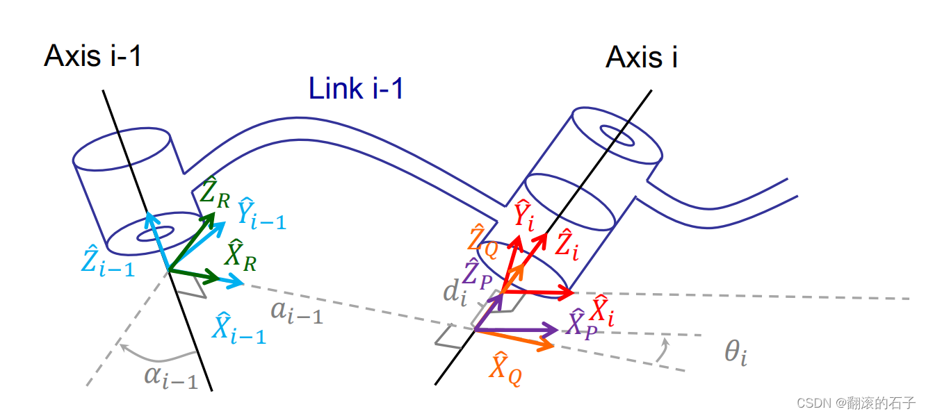
\(^{i-1}_i \!T\) 表示坐标系 \(\{i-1\}\) 到坐标系 \(\{i\}\) 的变换矩阵,i 从 1 开始
- 调整 \(Z\) 轴,绕 \(X\) 旋转——坐标系 \(\{i-1\}\) 绕 \(X_{i-1}\) 轴旋转连杆扭转角 \(\alpha_{i-1}\) 到达坐标系 \(\{R\}\)
- 沿着 \(X\) 轴平移——坐标系 \(\{R\}\) 沿着 \(X_R\) 轴移动连杆长度 \(a_{i-1}\) 到达坐标系 \(\{Q\}\)
- 调整 \(X\) 轴 , 绕 \(Z\) 旋转——坐标系 \(\{Q\}\) 绕 \(Z_Q\) 轴旋转关节角 \(\theta_i\) 到达坐标系 \(\{P\}\)(因为坐标系的方向是根据公垂线段定义的,所以由于下一个关节的方向不一致,所以原来的坐标系转过来的时候,需要向公垂线段的方向旋转一下)
- 沿着 \(Z\) 轴平移——坐标系 \(\{P\}\) 沿着 \(Z_P\) 轴移动连杆轴距 \(d_i\) 到达坐标系 \(\{i\}\)
理解变换中的变量和不变量
\(a_{i-1}\) 和 \(\alpha_{i-1}\) 是固定不变的参数,不会随着 关节 i 的运动而变化(这里这里说的是关节 i 和关节 \(i-1\) 的关系)
这样画可能可以理解关节 i 的行为不会影响之前的关节参数。 而且要注意:关节的旋转是指绕轴进行转动,而不是轴本身进行转动,第一次看的时候在这里有误区
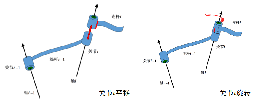
- 若关节 i 是转动关节,则 \(d_i\) 是固定不变的参数,\(\theta_i\) 是会随着关节 i 的运动而变化的关节变量,即:3 个连杆参数 \(a_{i-1}, \alpha_{i-1}, d_i\);1 个关节变量 \(\theta_i\)
- 若关节 i 是滑动关节,则 \(\theta_i\) 是固定不变的参数,\(d_i\) 是会随着关节 i 的运动而变化的关节变量,即:3 个连杆参数 \(a_{i-1}, \alpha_{i-1}, \theta_i\);1 个关节变量 \(d_i\)
一个有 \(N\) 个关节的串联机构,有 \(4N\) 个运动学参量,其中 \(3N\) 个是连杆参数、\(N\) 个是关节变量,它们包含了串联机构的全部空间几何信息
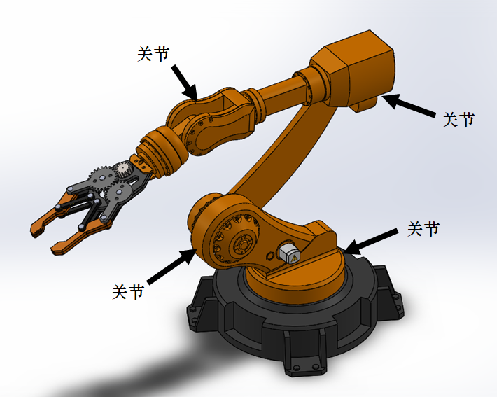
什么是关节和连杆
这里可以举一个小小的例子,比如下面的图片,黑色箭头地方是关节,将关节连起来的是连杆
题型 
\(a_i\) 的求解:相当于求异面直线之间的距离,可以采用
列写运动学参量表 
注意坐标系轴要建立正确
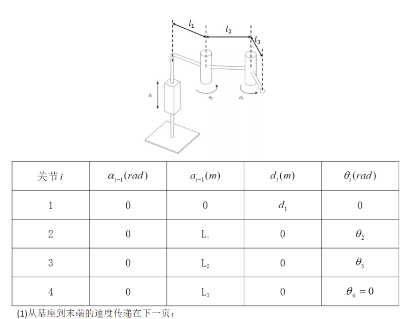
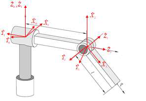
下图所示为一个 3 关节串联机械臂,该臂的末端装有吸盘作为操作工具。试在此机构上建立几何连杆、写出各连杆参数的值并列出各关节变量
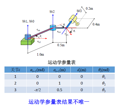
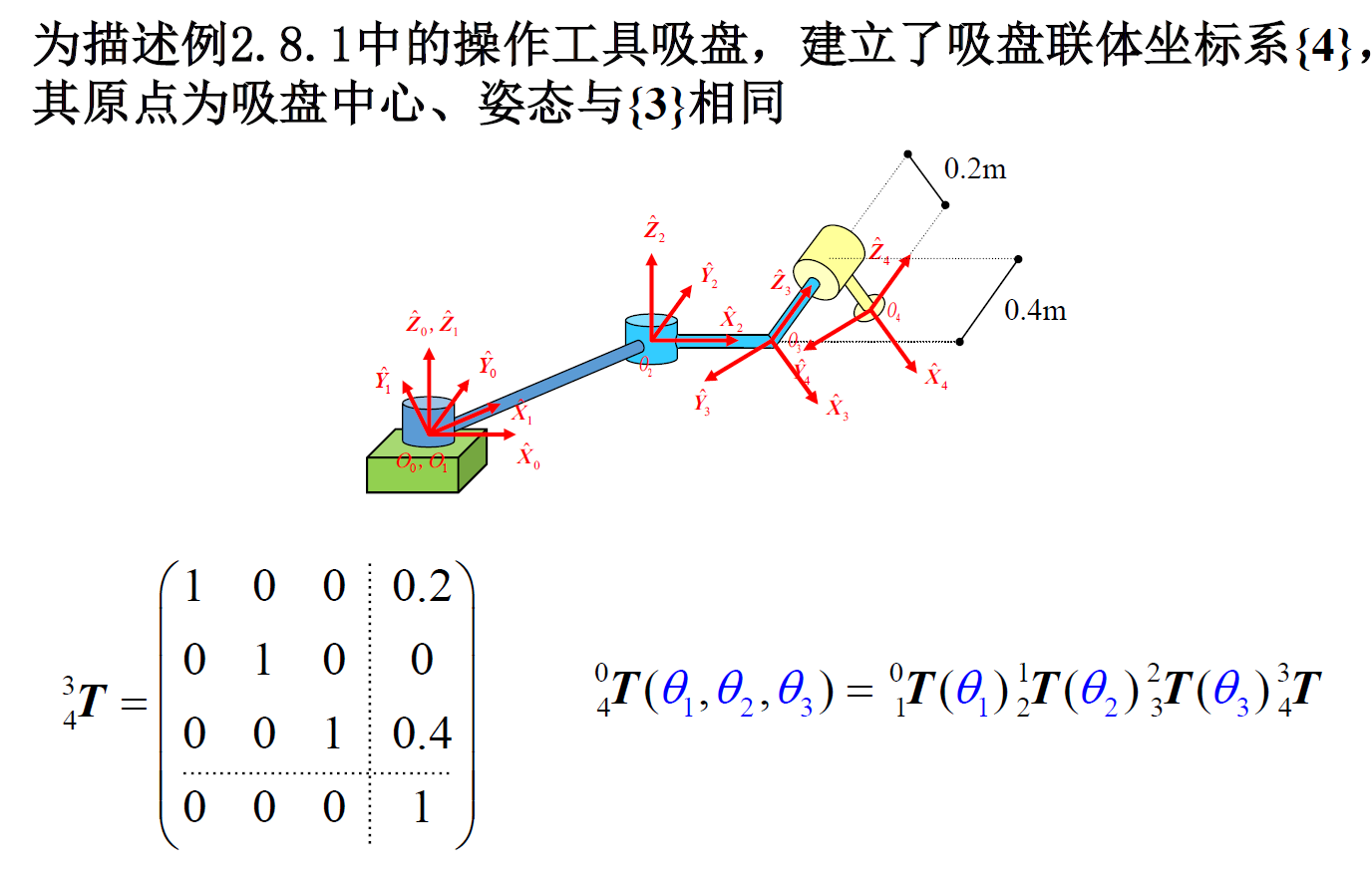
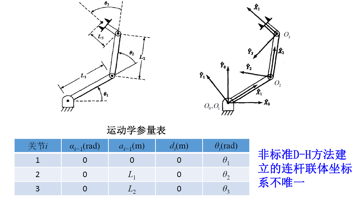
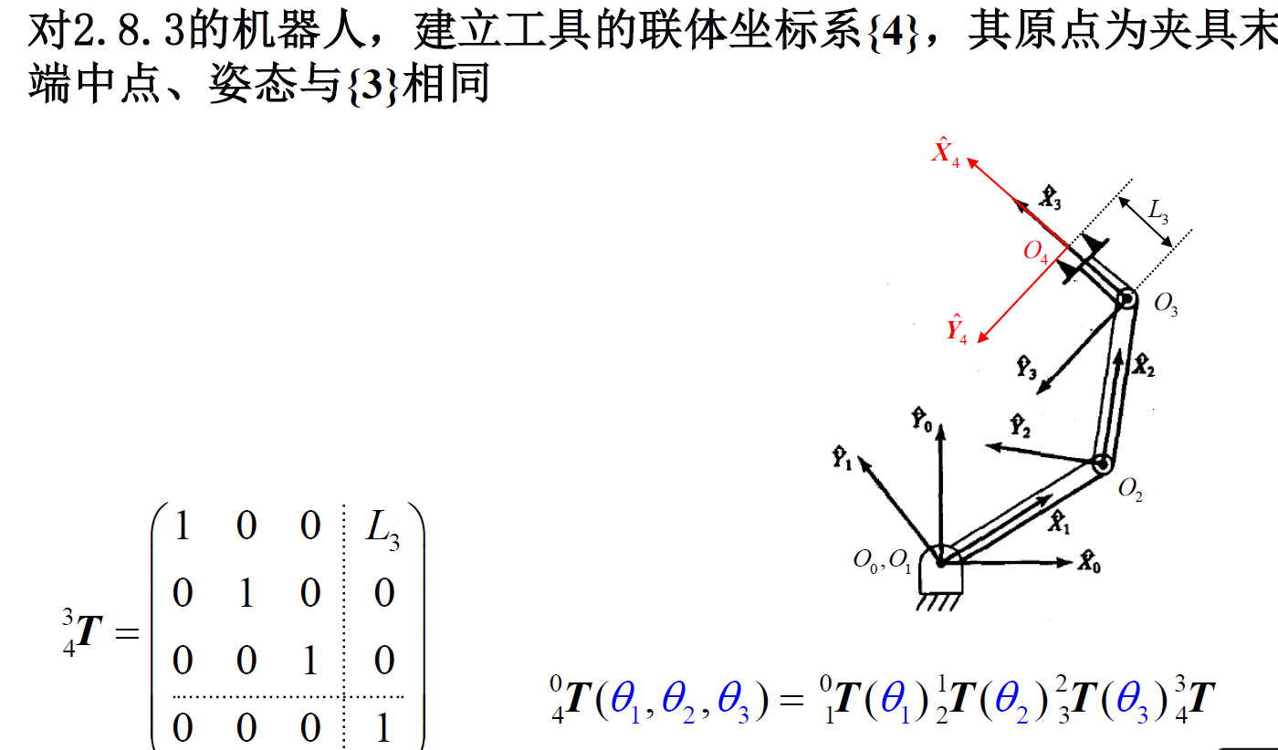
采用非标准 D-H 方法建立如图机器人的连杆联体坐标系

如果两个轴是平行的,在化简的时候可以使用和角公式进行化简(相当与把两个旋转变成一个等效的角度)
由于关节 2 和关节 3 是平行的,所以 \(^1T_2\) 和 \(^2T_3\) 的乘积可以用简化的表达式表示:
其中,\(c_{23} = \cos(\theta_2 + \theta_3)\),\(s_{23} = \sin(\theta_2 + \theta_3)\)。 这种简化在机器人运动学中非常有用,尤其是在处理具有平行关节的机械臂时。
列写齐次变换矩阵 
写齐次变换矩阵的时候,可以从基向量表出的角度进行。使用原坐标系表示现在坐标系的基
这样在 \(\alpha_{i-1}\) 为 0 或 \(\pm\frac{\pi}{2}\) 的时候,可以简化计算。
基向量表出可以看这个视频理解
求末端位置与姿态 
方法 1: 几何法转换为三角函数问题(仅适用于平面问题 , 即 \(\alpha_i\) 为 0 的时候,比较方便)
方法 2: 矩阵法(适用于任意维度)
其中,向量 \(\vec{P}\) 代表了机器人末端相对于机器人基座的位置,矩阵 \(R\) 代表了机器人末端相对于机器人基座的姿态(如果要求解角度的话,相当于旋转矩阵转换为欧拉角)
Casio fx-991 CNX 计算器的矩阵计算方法需要掌握
使用 Matlab 求解 
给定 DH 参数表,计算 \(^0_N\mathrm{T}\)
在化简的过程当中,常常苦恼化简太慢的问题。而且 casio 等计算器并不能处理带符号的化简。在室友的介绍下,学了一下 Matlab 的符号计算方法,还是比较好用的。
使用 Matlab 的在线编辑器
function T_final = compute_DH(DH_params)
    n = size(DH_params, 1);  % Number of joints
    T_final = eye(4);

    for i = 1:n
        % Extract DH parameters for joint i, attention the order!
        theta_i = DH_params(i, 4);
        d_i = DH_params(i, 3);
        a_i_minus_1 = DH_params(i, 2);
        alpha_i_minus_1 = DH_params(i, 1);

        T_i = [
            cos(theta_i), -sin(theta_i), 0, a_i_minus_1;
            sin(theta_i) * cos(alpha_i_minus_1), cos(theta_i) * cos(alpha_i_minus_1), -sin(alpha_i_minus_1), -sin(alpha_i_minus_1) * d_i;
            sin(theta_i) * sin(alpha_i_minus_1), cos(theta_i) * sin(alpha_i_minus_1), cos(alpha_i_minus_1), cos(alpha_i_minus_1) * d_i;
            0, 0, 0, 1
        ];
        fprintf('T_%d = \n', i);
        disp(T_i);
        T_final = T_final * T_i;
    end
    fprintf('Final Transformation Matrix T = \n');
    disp(T_final);
end
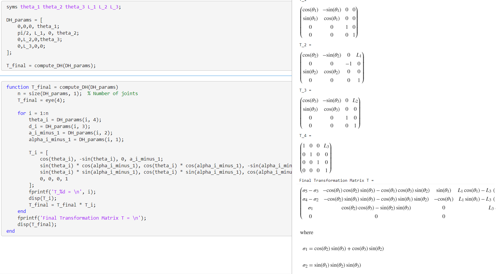
syms theta_1 theta_2 theta_3 L_1 L_2 L_3;

# order: alpha,a,d,theta
DH_params = [
    0,0,0, theta_1;
    pi/2, L_1, 0, theta_2;
    0,L_2,0,theta_3;
    0,L_3,0,0;
];

T_final = compute_DH(DH_params);
效果
例题 
3-3 RPR
3-3 下图所示为某 3 自由度机器人 (RPR)。 (1)试在此机器人上用非标准D-H方法建立连杆联体坐标系并写出运动学参量表 (2)求出该机器人用齐次变换矩阵形式表示的运动学方程
运动学参量表
| \(i\) | \(\alpha_{i-1}\)(rad) | \(a_{i-1}\)(m) | \(d_{i}\)(m) | \(\theta_{i}\)(rad) |
|---|---|---|---|---|
| 1 | 0 | 0 | 0 | \(\theta_{1}\) |
| 2 | \(\pi/2\) | 0 | \(d_{2}\) | \(\pi/2\) |
| 3 | \(\pi/2\) | 0 | 0 | \(\theta_{3}\) |
运动学方程
3-4 RPR
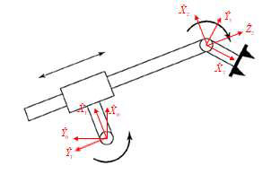
3-4 如图 3-19 所示的机器人,由两个转动关节与一个滑动关节组成,其各连杆的运动被约束在一个平面内。请:
(1) 试在此机器人上用非标准 D-H 方法建立连杆联体坐标系并写出运动学参量表;
(2) 求出该机器人用齐次变换矩阵形式表示的运动学方程。
运动学参量表
| \(i\) | \(\alpha_{i-1}\)(rad) | \(a_{i-1}\)(m) | \(d_{i}\)(m) | \(\theta_{i}\)(rad) |
|---|---|---|---|---|
| 1 | 0 | 0 | 0 | \(\theta_{1}\) |
| 2 | \(\pi/2\) | \(l_{1}\) | \(d_{2}\) | 0 |
| 3 | \(-\pi/2\) | 0 | 0 | \(\theta_{3}\) |
运动学方程
3-5
略
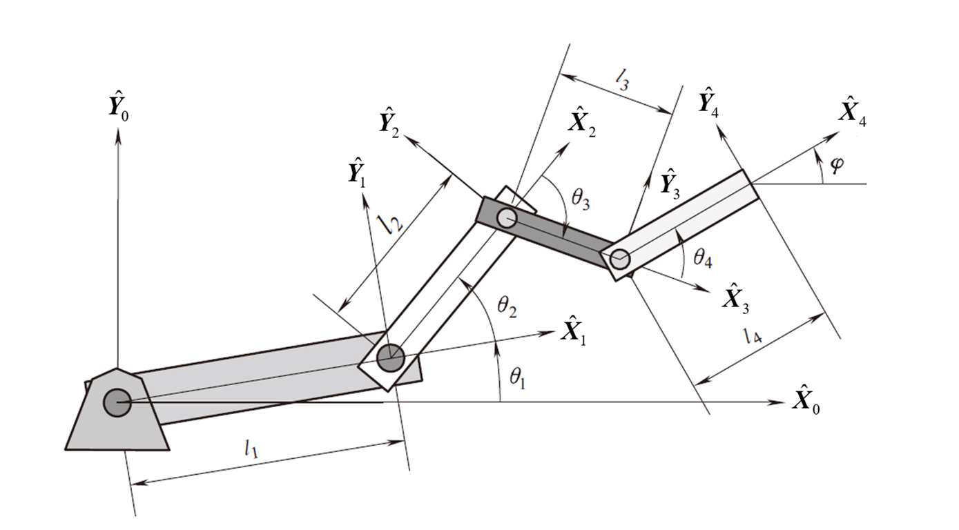
3-6 4R 平面 
4R 平面机器人如下图所示,其连杆联体坐标系已标在图中。试求:
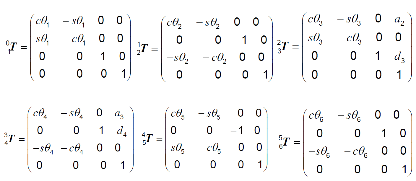
(1) 每个坐标系变换矩阵 \(_i^{i-1}\boldsymbol{T},i=1,2,3,4\) ;
(2) 末端执行器的全局坐标;
(3) 末端执行器的方位 \(\varphi\)。
实验课机械臂 6R 
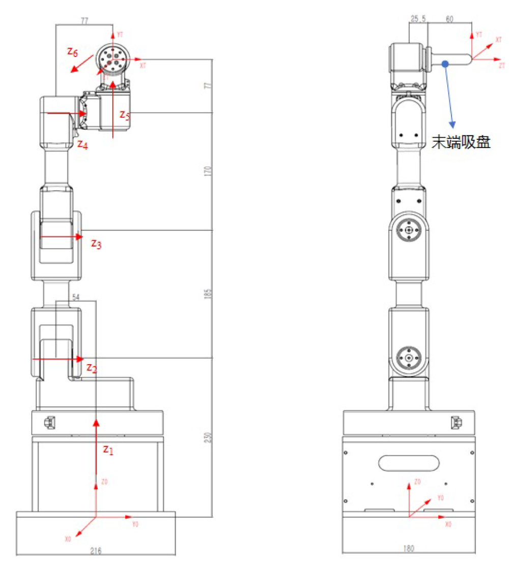
| \(\alpha\) | \(a\) | \(d\) | \(\theta\) | |
|---|---|---|---|---|
| 1 | 0 | 0 | 0.23 | \(\theta_1\) |
| 2 | \(-\pi/2\) | 0 | -0.054 | \(\theta_2-\pi/2\) |
| 3 | 0 | 0.185 | 0 | \(\theta_3\) |
| 4 | 0 | 0.170 | 0.077 | \(\theta_4+\pi/2\) |
| 5 | \(\pi/2\) | 0 | 0.077 | \(\theta_5+\pi/2\) |
| 6 | \(\pi/2\) | 0 | 0.0855 | \(\theta_6\) |
5-7 RRR
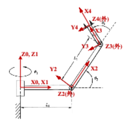
| 连杆 | \(\alpha_{i-1}\) | \(a_{i-1}\) | \(d_i\) | \(\theta_i\) |
|---|---|---|---|---|
| 1 | 0 | 0 | 0 | \(\theta_1\) |
| 2 | \(\frac{\pi}{2}\) | \(l_1\) | 0 | \(\theta_2\) |
| 3 | 0 | \(l_2\) | 0 | \(\theta_3\) |
由 DH 参数可以得到变换矩阵
5-9 PRR