Arduino
约 1305 个字 202 行代码 预计阅读时间 8 分钟
资源 
Built-in Examples | Arduino Documentation
配置 
IDE 下载 
下载对应版本的 IDE 即可
IDE 汉化 
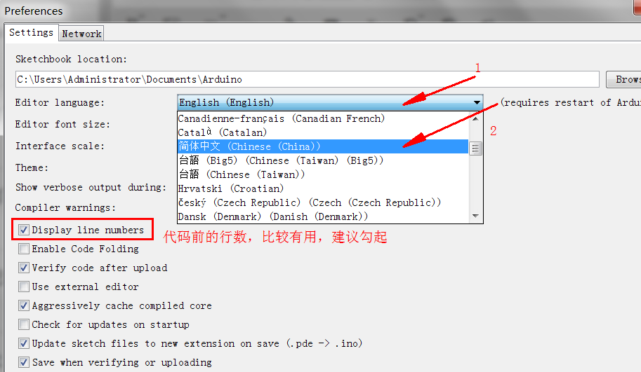
打开 arduino,然后点击File——>Preference,按图 3 顺序点击设置,然后重启,就可以设置成中文了
IDE 库的下载和导入 
- 直接下载
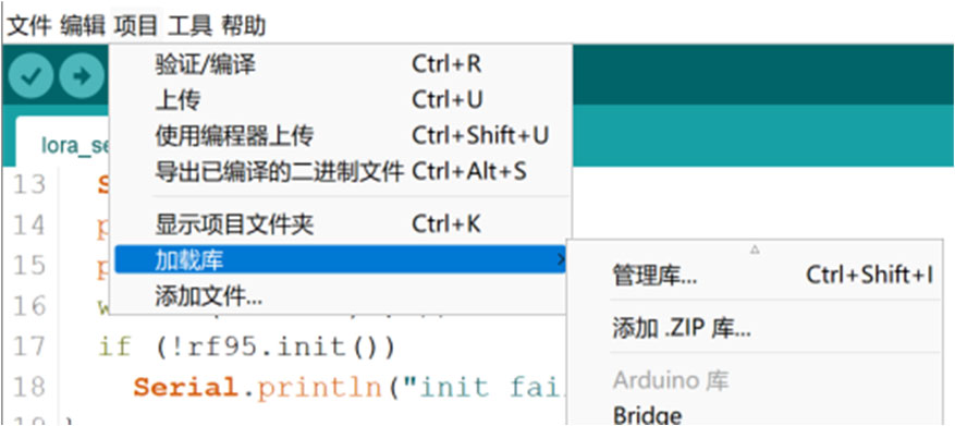
- 导入 zip 库 : 点击左上角“项目” -> “加载库” -> “添加 .ZIP 库” 然后选择下载的 zip 文件即可
vscode 中 Arduino IDE 插件 
- 保证 Arduino IDE 下载完成
- 下载插件

Python 固件烧录 
简单例程 
LED 闪烁 
This example uses the built-in LED that most Arduino boards have. This LED is connected to a digital pin and its number may vary from board type to board type.
void setup() {
  // initialize digital pin LED_BUILTIN as an output.
  pinMode(LED_BUILTIN, OUTPUT);
}

// the loop function runs over and over again forever
void loop() {
  digitalWrite(LED_BUILTIN, HIGH);  // turn the LED on (HIGH is the voltage level)
  delay(1000);                      // wait for a second
  digitalWrite(LED_BUILTIN, LOW);   // turn the LED off by making the voltage LOW
  delay(1000);                      // wait for a second
}
int ledPin = 13;  // LED连接到数字引脚13

void setup() {
  pinMode(ledPin, OUTPUT);  // 设置LED引脚为输出
}

void loop() {
  digitalWrite(ledPin, HIGH);  // 点亮LED
  delay(500);  // 延时500ms
  digitalWrite(ledPin, LOW);  // 熄灭LED
  delay(500);  // 延时500ms
}
串口通信 
串口通信最重要的参数是波特率、数据位、停止位和奇偶校验。
串口操作函数总结 
begin()
功能:初始化串口,通常放在 setup() 函数中,可配置串口参数。
语法:
Serial.begin(speed);
Serial.begin(speed, config);
speed:波特率,如 9600、115200 等。
- config:数据位、校验位和停止位配置,如 Serial.begin(9600, SERIAL_8E2)(8位数据,偶校验,2位停止位)。返回值:无。
end()
功能:结束串口通信,释放 Rx 和 Tx 引脚,使其可作为普通 IO 使用。
语法:
Serial.end();
返回值:无。
available()
功能:返回串口缓冲区中可读取的字节数(最大 64B
语法:
Serial.available();
返回值:可读取的字节数。
print()
功能:输出数据到串口,以 ASCII 码格式发送。
语法:
Serial.print(val);
Serial.print(val, format);
val:要输出的数据,任意类型。
- format:输出格式,如 BIN(二进制)、OCT(八进制)、DEC(十进制)、HEX(十六进制) 或浮点数小数位数。
示例:
Serial.print(55, BIN);   // 输出 "110111"
Serial.print(55, OCT);   // 输出 "67"
Serial.print(55, DEC);   // 输出 "55"
Serial.print(55, HEX);   // 输出 "37"
Serial.print(3.1415926, 2); // 输出 "3.14"
Serial.print("Hello!");  // 输出 "Hello!"
println()
功能:与 print() 类似,但输出后自动换行。
语法:
Serial.println(val);
Serial.println(val, format);
print()。返回值:输出的字节数。
read()
功能:读取串口数据(一个字节
语法:
Serial.read();
返回值:读取的字节,若无数据则返回
-1。
readBytes()
功能:从串口读取指定长度的数据存入数组,超时退出。
语法:
Serial.readBytes(buffer, length);
buffer:存储数据的数组(char[] 或 byte[])。
- length:读取的字节数。返回值:成功读取的字节数,若无数据则返回
0。
peek()
功能:读取串口缓冲区的第一个字节,但不删除。
语法:
Serial.peek();
返回值:缓冲区第一个字节数据,若无数据返回
-1。
write()
功能:以字节形式发送数据到串口。
语法:
Serial.write(val);
Serial.write(str);
Serial.write(buf, len);
val:单个字节数据。
- str:String 类型数据。
- buf:数据数组。
- len:数据长度。返回值:输出的字节数。
通信例程 
// 读取字符串
void setup(){
  Serial.begin(9600);
}

void loop(){
  String inString="";
  while(Serial.available()>0){
    inString += char(Serial.read());
    delay(10);      // 延时函数用于等待字符完全进入缓冲区,可以尝试没有延时,输出结果会是什么
  }
  // 检查是否接收到数据,如果接收到数据,则输出该数据
  if(inString!=""){
    Serial.print("Input String:");
    Serial.println(inString);
  }
}
int ledPin = 13;  // LED连接到数字引脚13
String inputString = "";  // 用于存储串口输入的字符串

void setup() {
  pinMode(ledPin, OUTPUT);  // 设置LED引脚为输出
  Serial.begin(9600);  // 初始化串口通信
}

void loop() {
  // 检查串口是否有数据输入
  if (Serial.available() > 0) {
    char incomingChar = Serial.read();  // 读取串口输入的字符
    inputString += incomingChar;  // 将字符添加到输入字符串中

    // 如果接收到"On"或者"1",点亮LED
    if (inputString == "On" || inputString == "1") {
      digitalWrite(ledPin, HIGH);  // 点亮LED
      Serial.println("LED is ON");  // 输出状态
    }
    // 如果接收到"Off"或者"0",熄灭LED
    else if (inputString == "Off" || inputString == "0") {
      digitalWrite(ledPin, LOW);  // 熄灭LED
      Serial.println("LED is OFF");  // 输出状态
    }

    inputString = "";  // 清空输入字符串
  }
}
两个 Arduino 通信 
中断 
Interrupts are useful for making things happen automatically in microcontroller programs and can help solve timing problems. Good tasks for using an interrupt may include reading a rotary encoder, or monitoring user input.
If you wanted to ensure that a program always caught the pulses from a rotary encoder, so that it never misses a pulse, it would make it very tricky to write a program to do anything else, because the program would need to constantly poll the sensor lines for the encoder, in order to catch pulses when they occurred. Other sensors have a similar interface dynamic too, such as trying to read a sound sensor that is trying to catch a click, or an infrared slot sensor (photo-interrupter) trying to catch a coin drop. In all of these situations, using an interrupt can free the microcontroller to get some other work done while not missing the input.
int pinInterrupt = 2; // 接中断信号的引脚

void onTouch()
{
  Serial.println("[info] finger touch");
}

void onLeave()
{
  Serial.println("[info] finger leave");
}

void setup()
{
  Serial.begin(9600);
  Serial.println("[info] begin to work");

  pinMode( pinInterrupt, INPUT);// 设置管脚为输入

  // Enable中断管脚, 中断服务程序为onTouch(), 监视引脚变化
  attachInterrupt(digitalPinToInterrupt(pinInterrupt), onLeave, FALLING);
  attachInterrupt(digitalPinToInterrupt(pinInterrupt), onTouch, RISING);
}

void loop()
{
  while(1);
}
按照触发方式分为下面四类:
- LOW to trigger the interrupt whenever the pin is low,
- CHANGE to trigger the interrupt whenever the pin changes value
- RISING to trigger when the pin goes from low to high,
- FALLING for when the pin goes from high to low.
定时器 
TimerOne 不仅可以完成定时器的功能,也封装了 PWM 的功能,功能上更加丰富。不过在代码可读性上来说,MsTimer2 更具优势
Arduino UNO 有三个定时器,
timer0:一个被 Arduino 的delay(),millis()和micros()使用的 8 位定时器timer1:一个被 Arduino 的Servo()库使用的 16 位定时器timer2:一个被 Arduino 的Tone()库使用的 8 位定时器
Actually,定时器的使用也有多种方式,常见的定时器使用方式有自定义触发、MsTimer2 库、TimeOne 库三种方式,但事实上,我们不推荐自定义编写定时器触发方式,如果你想使用操作寄存器这种复杂的方式,你就没必要使用 arduino
MsTimer2
MsTimer2 封装了 Timer2 的定时器,因为为第三方库,所以需要先安装 MsTimer2 库。
MsTimer2 | Arduino Documentation
| 每 500ms 让 13 引脚的 LED 灯亮一下 | |
|---|---|
1 2 3 4 5 6 7 8 9 10 11 12 13 14 15 16 17 | |
#include <MsTimer2.h>

int ledPin = 13;  // LED 连接到数字引脚 13
bool ledState = LOW;  // LED 状态(初始熄灭)
int interval = 400;  // 400ms 亮,600ms 灭

void toggleLED() {
  ledState = !ledState;  // 切换 LED 状态
  digitalWrite(ledPin, ledState);  // 设置 LED 状态
  Serial.println(ledState ? "LED is ON" : "LED is OFF");  // 通过串口输出状态
  MsTimer2::set(ledState ? 400 : 600, toggleLED);  // 设置下次定时
  MsTimer2::start();  // 重新启动定时器
}

void setup() {
  pinMode(ledPin, OUTPUT);  // 设置 LED 引脚为输出
  Serial.begin(9600);  // 初始化串口通信
  MsTimer2::set(interval, toggleLED);  // 设置定时器
  MsTimer2::start();  // 启动定时器
}

void loop() {
  // 主循环无须处理,LED 由中断定时控制
}
TimerOne
#include <TimerOne.h>

void callback()
{
    static boolean output = HIGH;
    digitalWrite(13, output);	// 状态翻转
    output = !output;
}

void setup()
{
    pinMode(13, OUTPUT);
    Timer1.initialize(500000); // initialize timer1, and set a 1/2 second period
    Timer1.pwm(9, 512); // setup pwm on pin 9, 50% duty cycle
    Timer1.attachInterrupt(callback); // attaches callback() as a timer overflow interrupt
}

void loop()
{

}
#include <TimerOne.h>

int ledPin = 13;  // LED 连接到数字引脚 13
bool ledState = LOW;  // LED 状态(初始熄灭)

void toggleLED() {
  ledState = !ledState;  // 切换 LED 状态
  digitalWrite(ledPin, ledState);  // 设置 LED 状态
  Serial.println(ledState ? "LED is ON" : "LED is OFF");  // 通过串口输出状态
  Timer1.initialize(ledState ? 400000 : 600000);  // 重新设置定时时间(us)
  Timer1.attachInterrupt(toggleLED);  // 绑定中断函数
}

void setup() {
  pinMode(ledPin, OUTPUT);  // 设置 LED 引脚为输出
  Serial.begin(9600);  // 初始化串口通信
  Timer1.initialize(400000);  // 设置定时 400ms(us)
  Timer1.attachInterrupt(toggleLED);  // 绑定中断函数
}

void loop() {
  // 主循环无须处理,LED 由中断定时控制
}
注意事项 
- 如果你使用了
MsTimer2库, 则pin11和pin3就不能再用做 PWM 输出了 ! 因为该pin3和pin11的 PWM 是靠timer2帮忙的 ! (tone()也是 ) - 注意
Servo.h库与TimerOne都是使用内部定时器timer1会影响pin 9,pin 10的 PWM tone()使用timer2定时器 ; 若使用Tone库的Tone对象 (Tone变量 ) 也是优先使用timer2定时器,若用两个Tone变量则timer1也会被用掉, 用三个Tone则连控制millis( )的timer0也会被用掉。- 别忘了,
timer0负责帮忙控制pin 5和pin 6的 PWM 输出。只要不去改变timer的Prescaler就不会影响其控制的 PWM pin, 但MsTimer2库与tone( )都会改变Prescaler